Arthur J. Stokes N8BN
The Gyrator II VLF receiver is described in another section of the SID equipment. The Minimal Gyrator II receiver described here is an attempt to show a lower parts cost receiver for solar monitoring that would be a suitable school project. The number of parts has been reduced to the essentials.
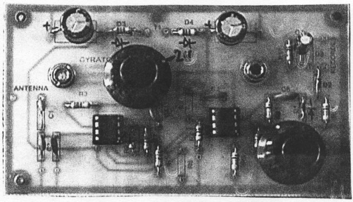
This simplified version eliminates the metal cabinet and expensive BNC connectors. Also eliminated is the metal working associated with drilling mounting holes in the cabinet. All parts are mounted on the circuit board. The only modification to the circuit board is the need to drill four holes to mount two connectors and two potentiometers. The basic circuit is the same as the previous Gyrator II circuit with the exception of the power supply. The previous Gyrator II used a center tapped 12 volt AC transformer and two diodes to form a bipolar power supply. Since there is no convenient mounting place on the board for this type of transformer, I decided to use a wall plug transformer. Radio Shack does not carry a center tapped 12 volt AC wall plug transformer. I modified the power supply circuit to use a 9 volt DC wall plug transformer. To simulate a center tap, I used two 180 ohm resistors in series across the 9 volt DC transformers, with the common center point connected to ground. This may seem like a short circuit, however only about 25 milliamps flow through the resistors. The two resistors nicely replace the diodes D4 and D5 in the original Gyrator II circuit. Capacitors C8 and C9 complete the power supply circuit. The white lead from the transformer is connected to the junction of .C9 and R15. This is the + voltage point. The white lead with a black tracer is connected to the junction of C8 and R14. This is the - voltage point. It would be well to check the polarity of the leads with a voltmeter before soldering.
Construction:
The circuit board is a new version with an overlay showing parts placement. The first 1/4 inch hole is made 3/4 of an inch from the left side of the board and 1 inch from the back edge. The second 1/4 inch hole is made 1 and a 1/4 inch from the right side and 7/8 inch from the back edge. The third hole is made with a 3/8 inch drill 1 and 3/4 inches from the left edge and 1 inch from the back of the board. The second 3/8 inch hole is made 3/4 inch from the right edge and 5/8 inch from the front edge of the board. The shafts on the potentiometers are usually long and should be cut off with a hacksaw to about 3/4 of an inch. Some small washers should be placed on the shafts to lift the pots slightly off the PC board to prevent shorting to the copper foil. All parts should be mounted on the PC board and soldered carefully before the pots are put in place. The pots should be rotated to position the tabs close to the corresponding points on the circuit board where the connections are to be made. Short pieces of bare copper wire are used to connect the pots. There is no need to use shielded wire since the connections are short. The 10K tuning pot is connected between ground and the end of R5. The 50K gain pot is connected between R7 and pin 1 of the second TL082 IC. There are no feedback problems with these short connections. The four corner mounting holes on the PC board were enlarged slightly and used to make legs that would allow the receiver to sit on a flat surface. Insulated standoffs form the legs. It was necessary to glue two together to make the 3/4 inch clearance needed. A cheaper alternative would be four 3/4 inch 6/32 screws and nuts to form the standoffs. The two 1/8 inch audio connectors replace the more expensive BNC . connectors. One is used as the antenna input with the outer sleeve connected to ground and the center pin connected to the 100 pfd C1 capacitor. The second audio connector is used for the recorder output with the outer sleeve connection to ground and the center pin connected to the junction of D2 and C7. This version uses ceramic capacitors available from Radio Shack. Although the Q of these capacitors is not as high as the polypropylene capacitors, they still provide sufficient selectivity for good tuning.
Performance:
This little receiver has worked very well. It has about the fewest number of parts that can make a workable VLF receiver. The tuning range is about from 17 kHz to 34 kHz.
The Gyrator II circuit board may be purchased from FAR Circuits, 18N640 Field Court, Dundee, IL 60118
References:
- Arthur J. Stokes, "A Gyrator Tuned VLF Receiver", Communications Quarterly, Spring 1994, pgs 24-26.
- Arthur J. Stokes, "A Gyrator Tuned VLF Receiver", SID Technical Bulletin, Vol. 5,1
- Arthur J. Stokes, "Gyrator II - An Improved Gyrator Tuned VLF Receiver", SID Technical Bulletin, Vol. 10,1 Available at www.aavso.org